Category Archives: Location Sound Gear Deconstruction

Location Sound Equipment deconstruction, repair and modification

Repairing a Broken Lectrosonics SMA Elbow Whip Antenna

leamj23
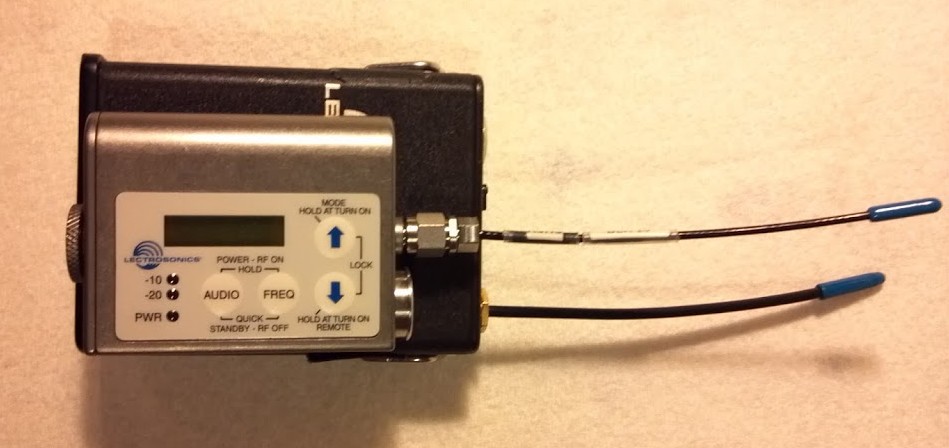
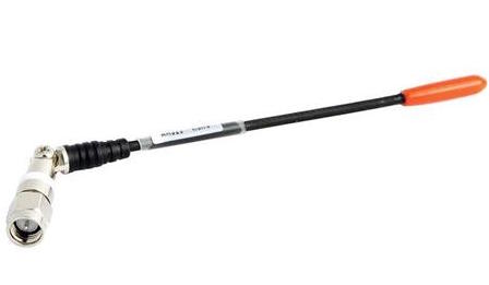
The Lectrosonics Elbow, or jointed whip antenna, has been the subject of some concern since their introduction with the SRa and subsequent rise in popularity. The pin in the antenna’s connector has a tendency to become detached internally from the elbow, breaking the connection between receiver and antenna.

Damn it! Another one!

The problem can go unnoticed, because Lectro’s diversity reception receivers have two antennas, and the opposite antenna  keeps the receiver working well most of the time. Eventually, the broken pin falls out, which can take a long time from the initial break. This visual indication is often the user’s only sign that the antenna is broken.  Of course, if the antenna is used on a  transmitter, and the results would be immediately apparent. However, the elbow antenna couldn’t have been intended to work on a transmitter worn by an actor. Why? The elbow exposes the antenna conductor, which can come in contact with the talent’s skin and sweat, severely de-tuning the antenna and possibly reducing range dramatically.  Not to mention, in stabbing into the talent’s backside, or stuffed in a pocket the elbow joint could be subject to subject to enough tourque to break the pin.

Lectrosonics has addressed this issue with testing of their jointed antennas, intentionally applying stress to the structure, and exploring means of strengthening the build. Their last announcement stated that 20 pounds of torque was required to break the connection. Therefore, the only reason they should break is due to abusive treatment. I suggest the break develops over time, as a result of reasonable, regular field use.

Apparently, Lectrosonics and/or their dealers have selectively been providing free-of-charge replacement antennas to those who bring in their broken units. My inquiry to the Lectro home office regarding the 8 or 10 broken units in my possession was met with “warranty limitation” issues. They explained that my antennas were over a year old, and therefore were no longer under warranty. I would have to buy new antennas at about $40 a piece.

After buying replacement whips (and abandoning the elbow antennas entirely), and also being somewhat of a DIY-er, I went about building my own whip antennas, using SMA connectors and steel antenna cable. Success came soon enough, but in toying with my handful of broken Lectrosonics Elbow Antennas, I wondered,  can a repair be possible?

Possibly… Here’s what happened next.

You’ll need to be good a soldering. Also have a small, table top vice. You’ll also need a Dremel tool with a miniscule drill bit (the kind for drilling circuit boards).  A Dremel sanding/cutting disc. A big pair of Vice-Grips. A small allen wrench. Good wire cutters. A means of measuring a few mm accurately. Some thick, solid tinned wire, like from a 1 watt resistor.

Use Thick WIre like from a 1 watt resistor. Don't use thin wire, like from a 1/4 watt resistor

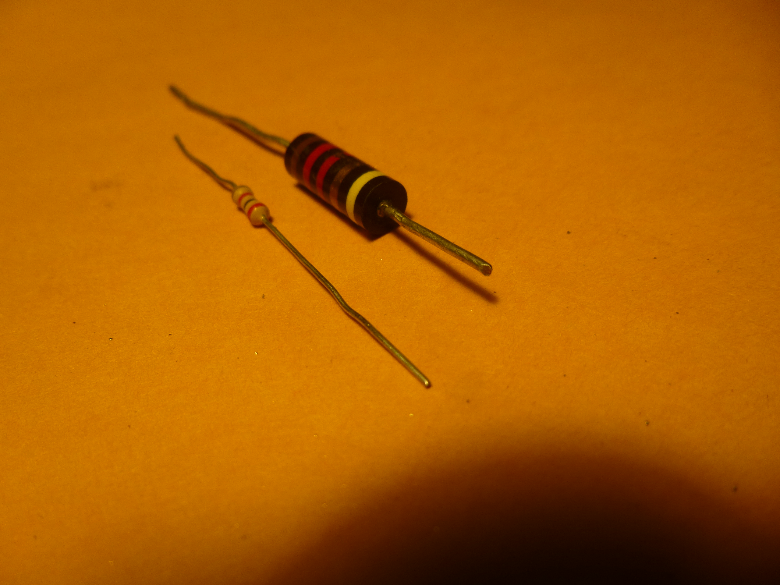
Use Thick WIre like from a 1 watt resistor. Don’t use thin wire, like from a 1/4 watt resistor

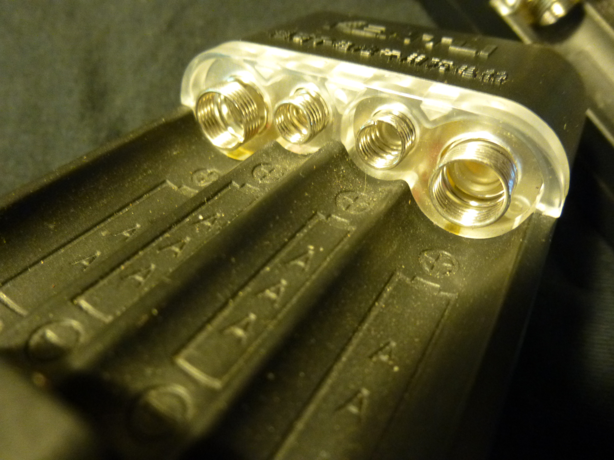
Have good eyesight or wear some headworn magnifiers.  You’ll need supply of pins from virgin SMA connectors from the various sources that sell these things. The Chinese ones are pretty cheap, Try www.aliexpress.com. For this project,  all you’ll need are the center pins that are included with the SMAs. For experimentation, I ordered 50 of them, in many different cable-size configurations. Most of the pins are the same from one kind of SMA to another. Use the pins that look like the ones in the photos, below. P1020672

P1020649
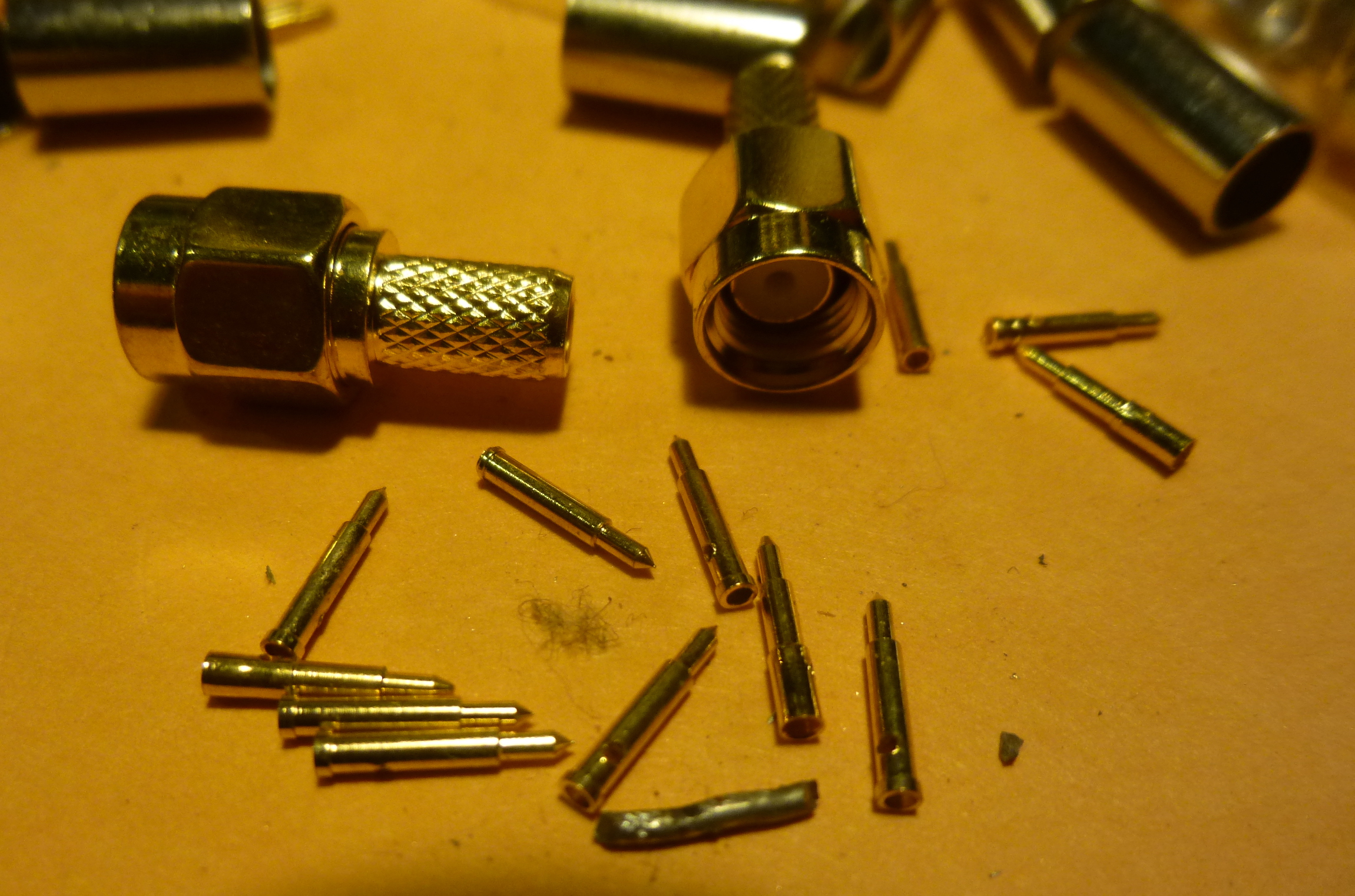
1. Plug in your soldering iron, dummy. P1020651

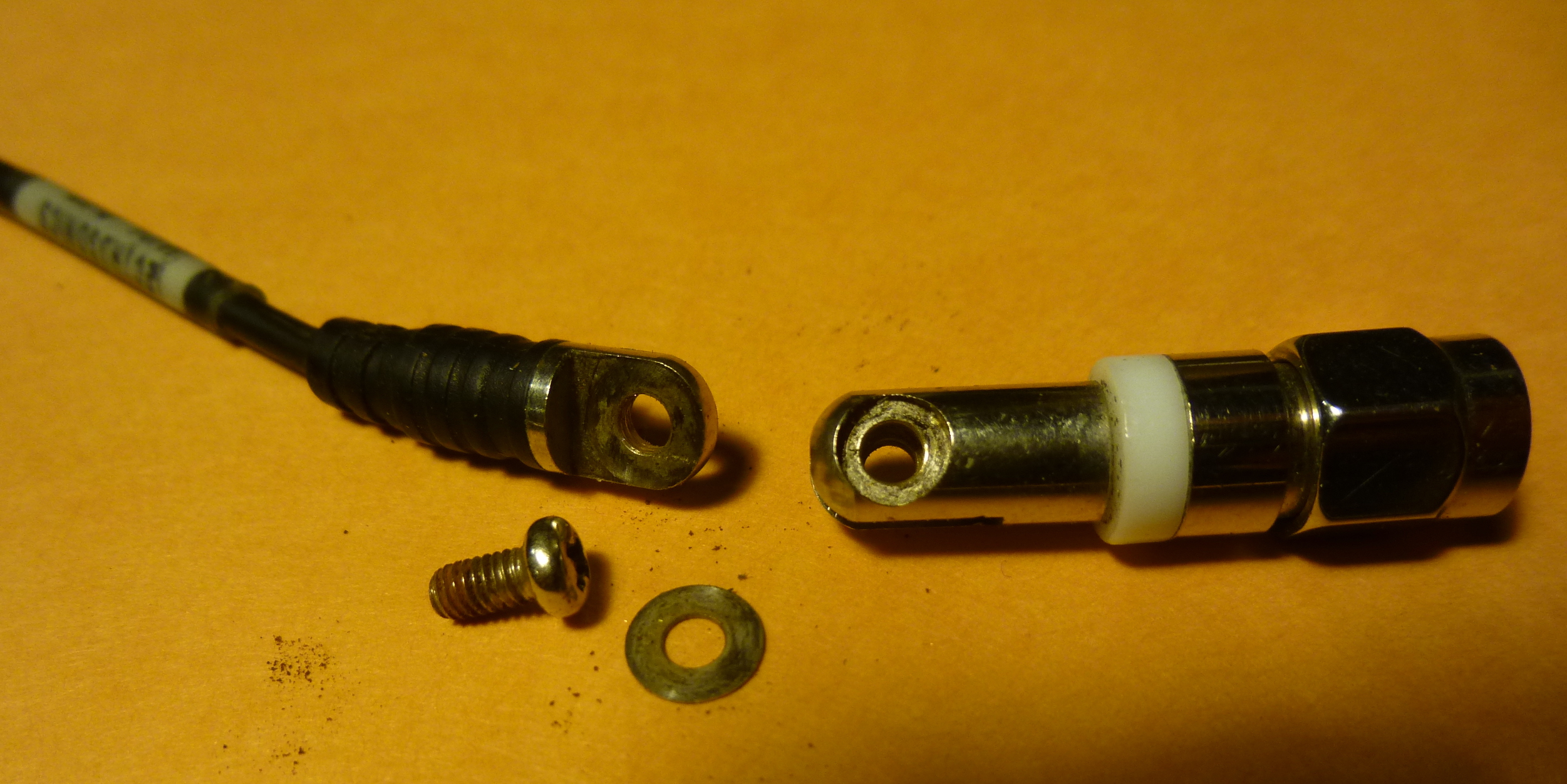
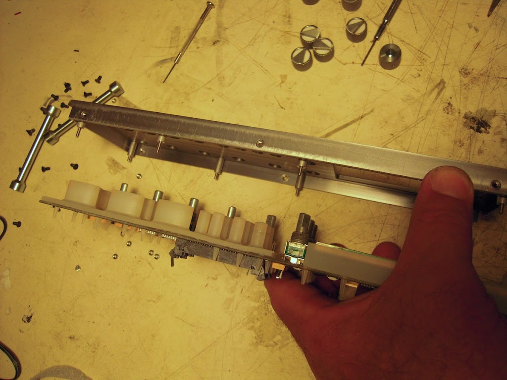
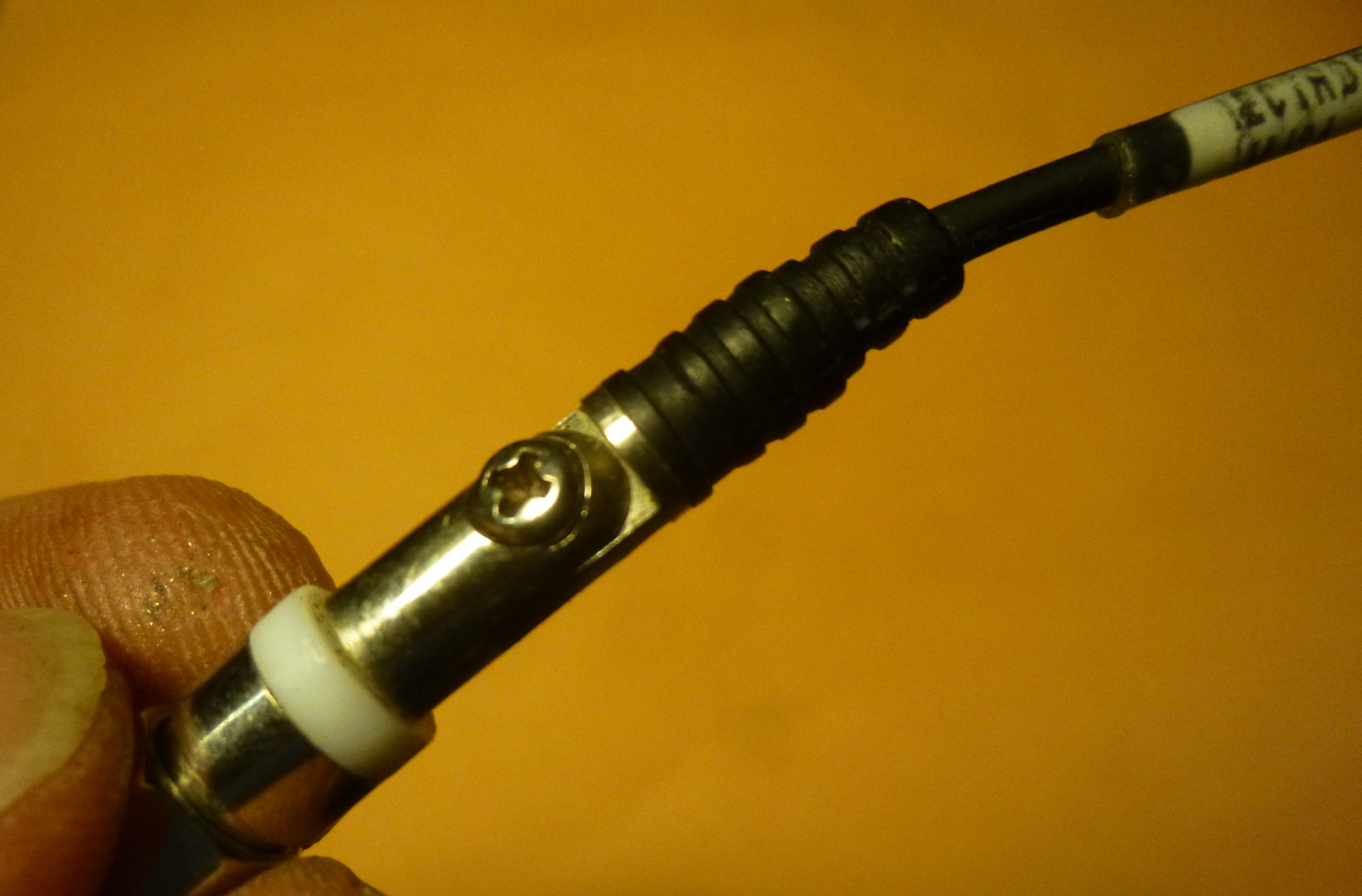
2.Remove the screw from the broken Lectrosonics antenna and remove the whip. There will be one or two washers in there, and a bunch of dirt and crap to clean. save all of it for reassembly later. P1020652

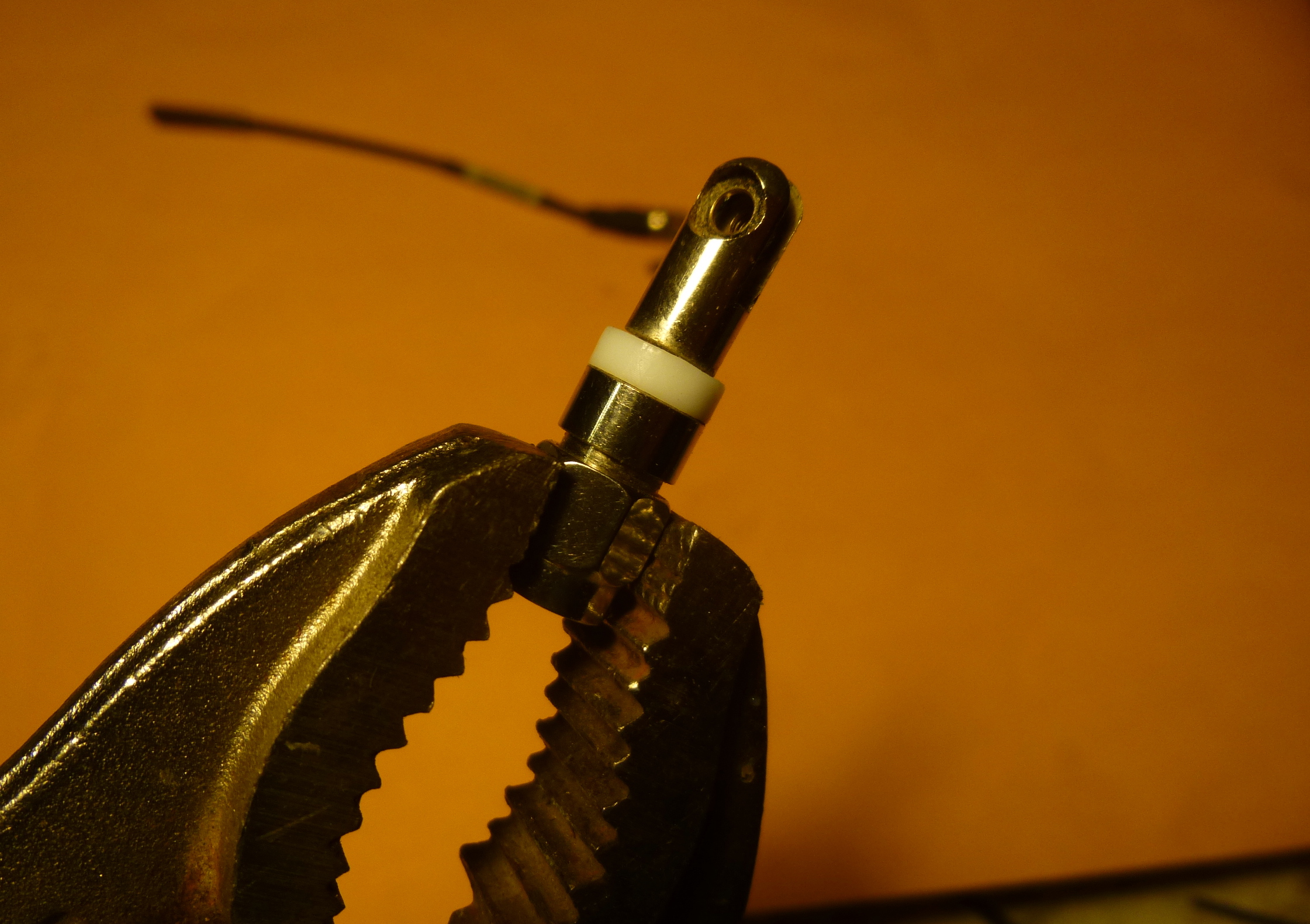
3. Clamp the SMA screw-on nut in the vice grips like so. Do not over tension, or you’ll squash the damn thing. P1020653

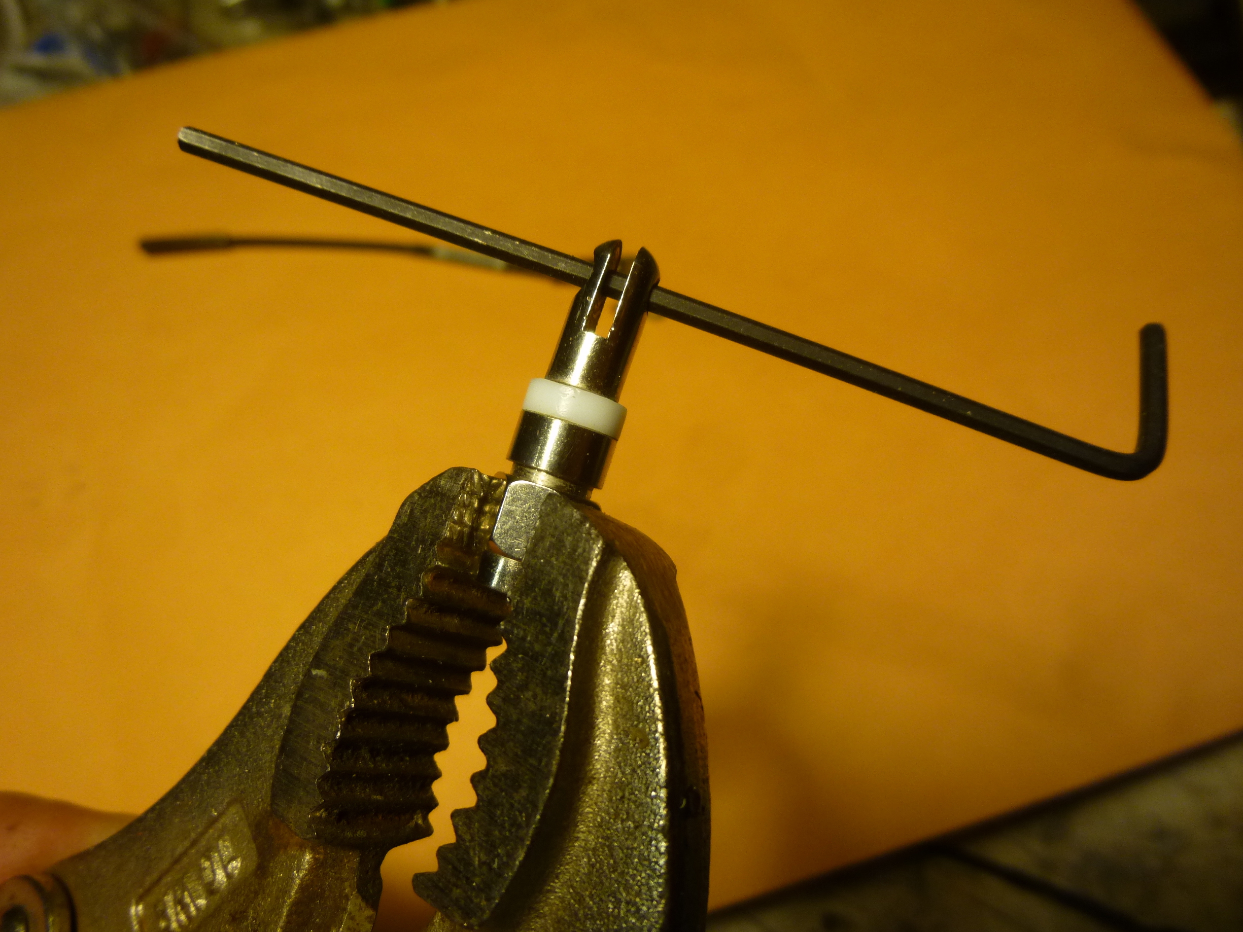
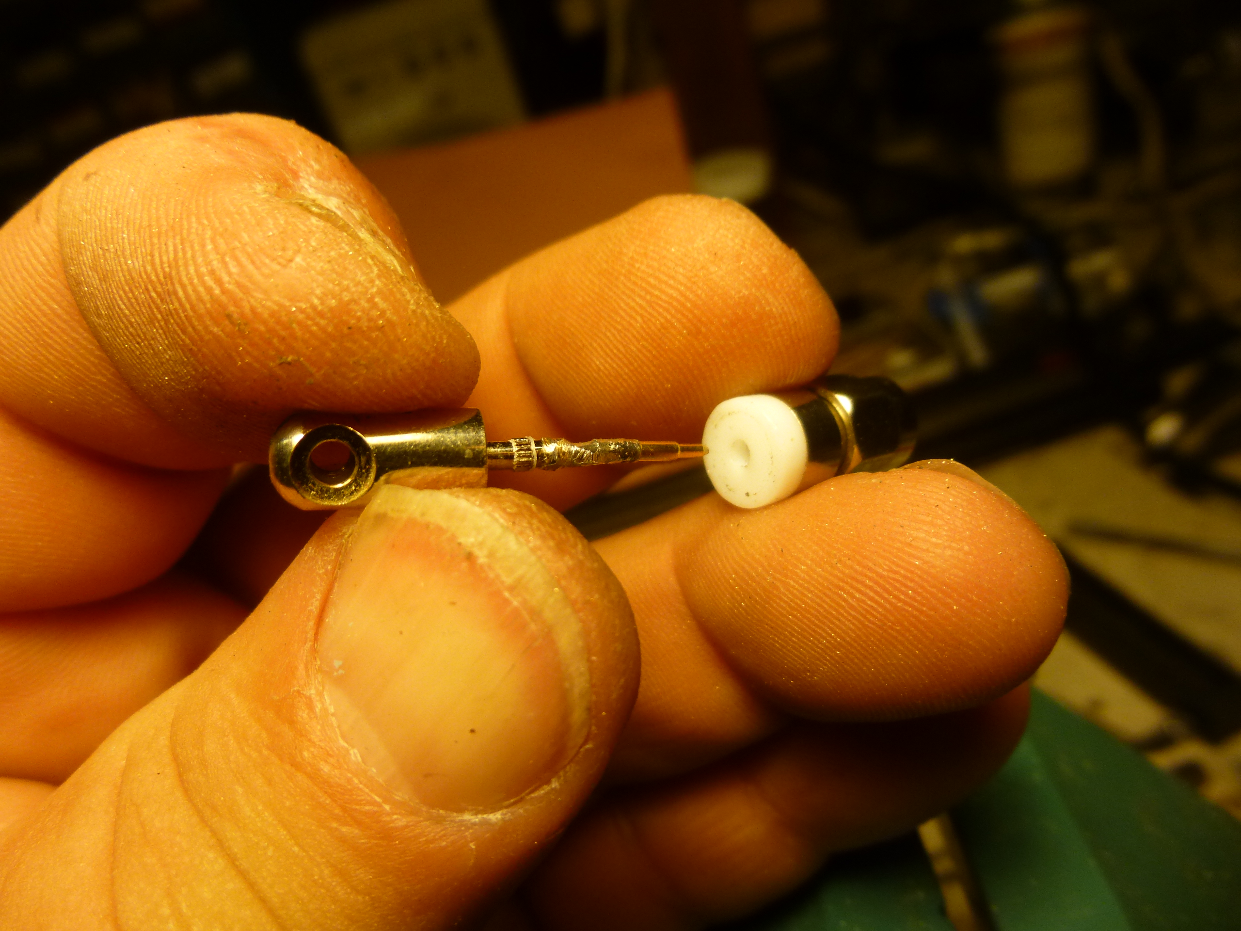
4. Insert an allen wrench (or something)  through the holes for the screw. This gives you some purchase on the center assembly to pull it out of the connector body. P1020654

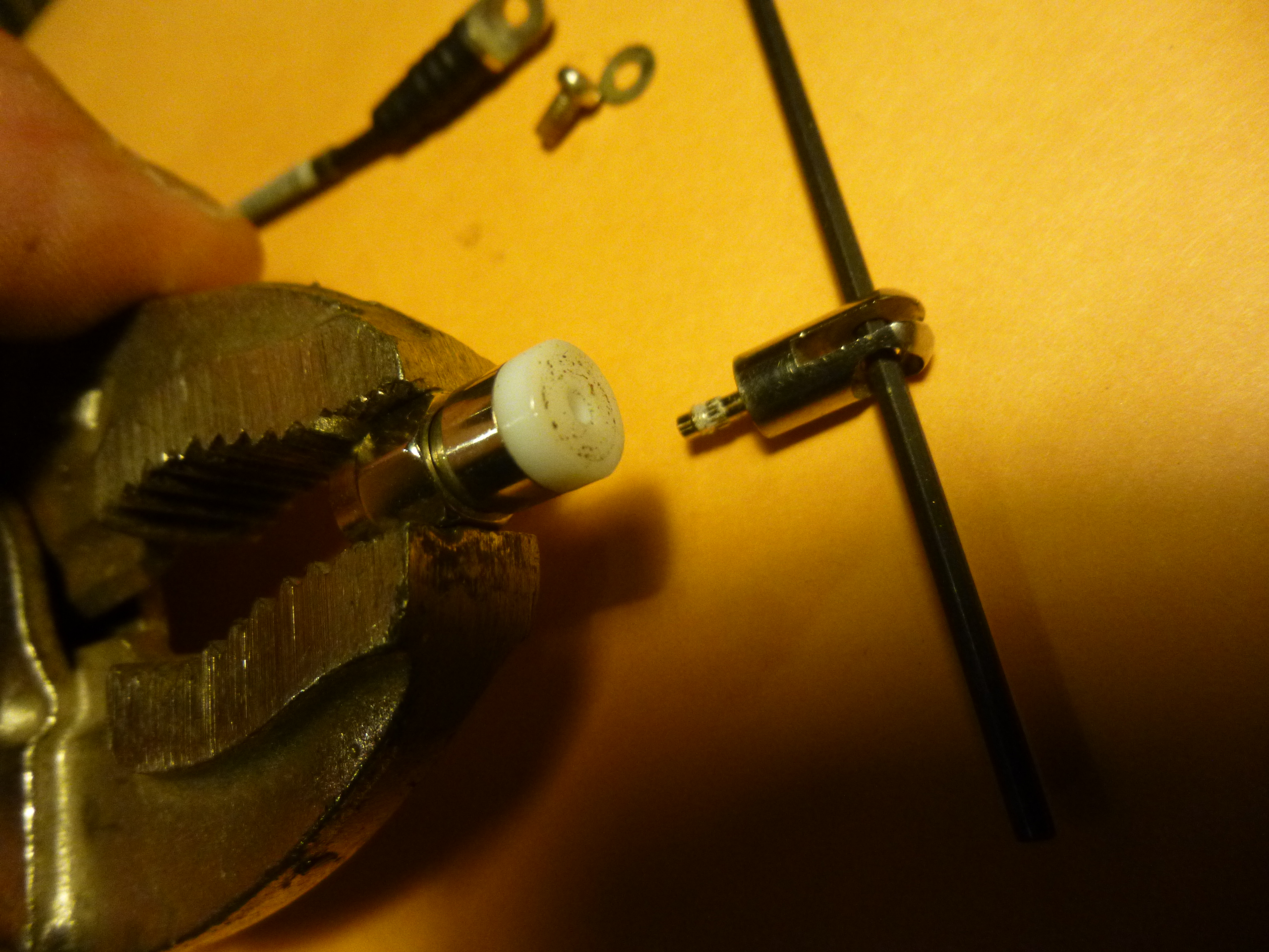
5. With the vice-grip in one hand and the allen wrench in the other, pull the two pieces apart, like you are un-corking a bottle of wine. Pull!  P1020655

P1020663

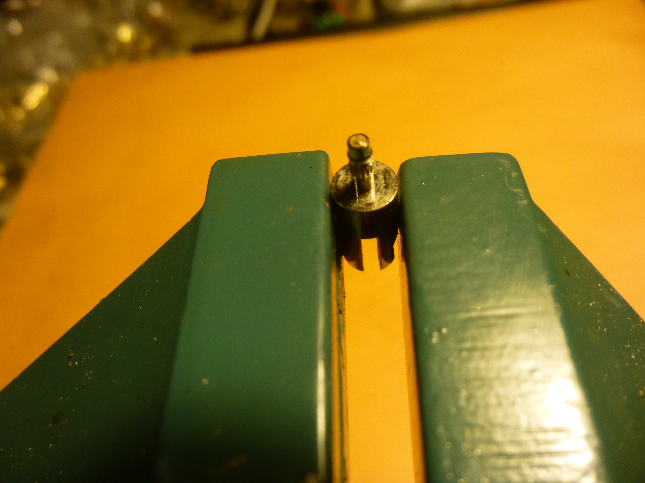
My solder is not black, it just looks that way in this pic.

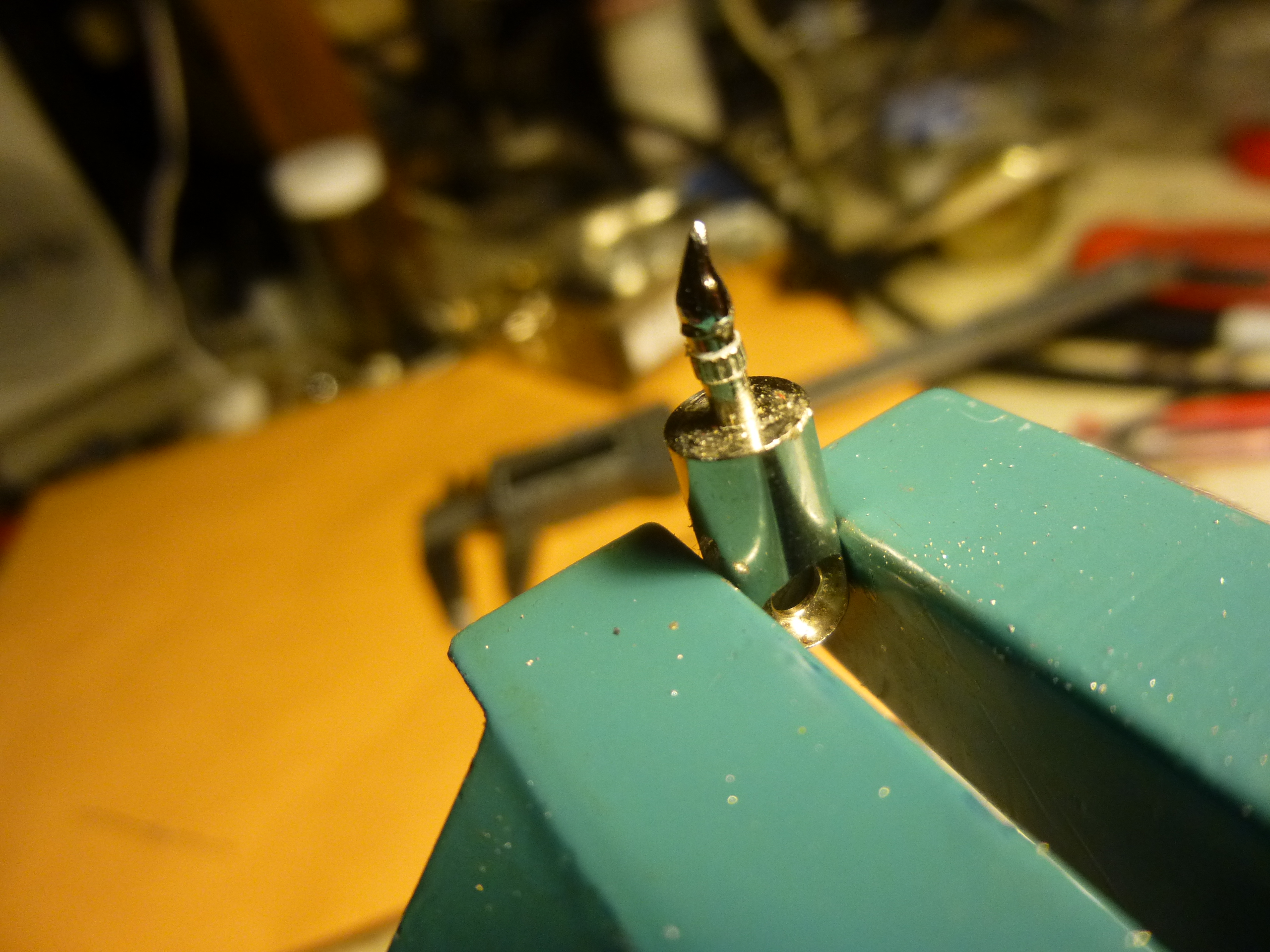
6. Insert the antenna top-piece in the vice, broken-pin-area facing up. ( I call this the spud). Use your Dremel tool with a circuit-board drill bit to create a hole in the top of the spud where the old pin broke off.P1020657 
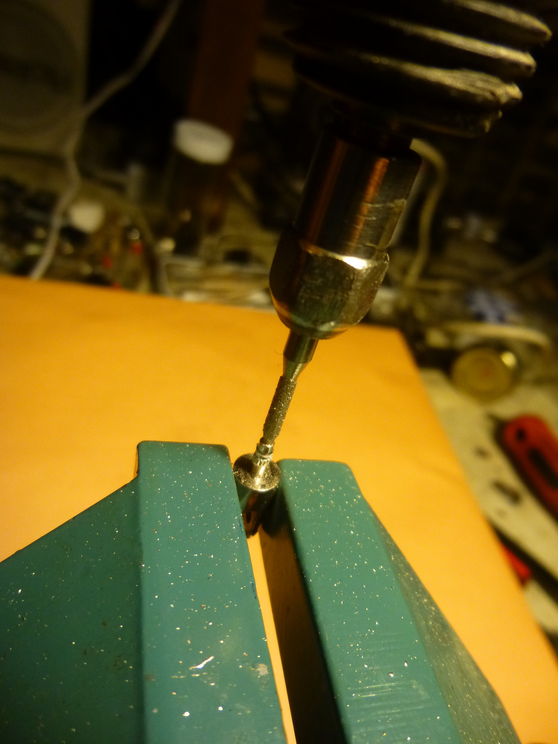
Make it as deep as you can, say 1/8 inch. Steady hands!                                Make sure the hole stays in the center of the spud.  Tin the hole with some solder. Use a little too much solder, its ok. You’ll file off the excess later (below).

7. Remove the top piece from the vice, set aside, and Insert your thick wire (like from the 1 watt resistor) in the vice. Slide the new SMA pin over the wire. Solder the pin to the wire. Make a damn good connection. P1020660

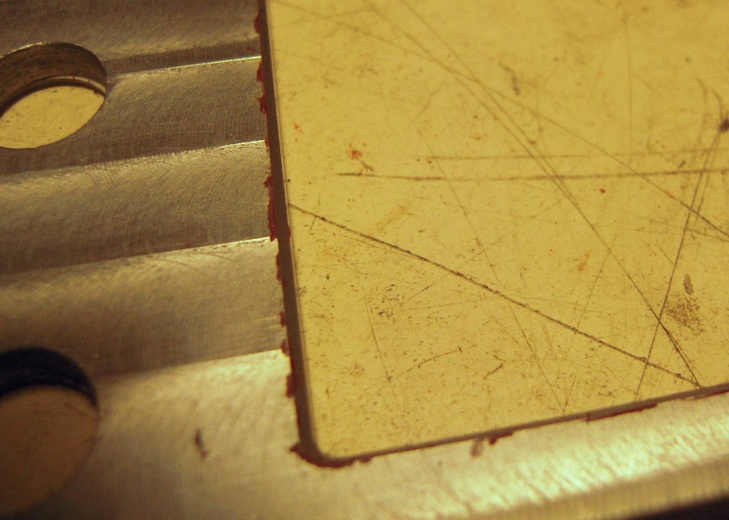
8. Measure at least 10.40 mm from the top of the pin and cut the thick wire at that point. This length may vary, depending on how deep a hole you drilled in the spud previously. Regardless, the tip of the new pin should end up 10.30 mm away from where the old pin broke off the spud. Thats .403 inches.  Cut and trim the thick wire so the pin-tip arrives at this length. File down the cut point to smooth and round, OK?

9. Put your drilled spud back in the vice. Insert the pin/wire combo into the hole in the spud. Again, make sure the distance from the tip of the pin to where the pin broke off is 10.30mm.P1020662

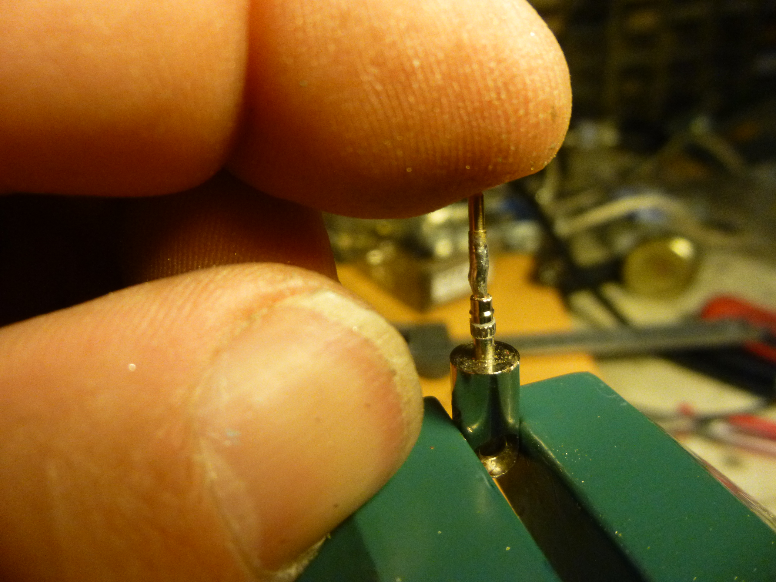
10. Holding the pin up straight in the spud, solder the wire to the spud. Solder gets weaker and shitty-er the longer it stays hot, so quickly solder up a damn good connection between the pin, wire, and spud. The thick wire will add some flexibility, length and integrity to the connection. Test the strength of the solder job, but don’t bend the shit out of it in testing!  The wire will be thick enough to allow you to push top assembly back into the SMA housing, without smashing or bending the wire in the process. P1020664

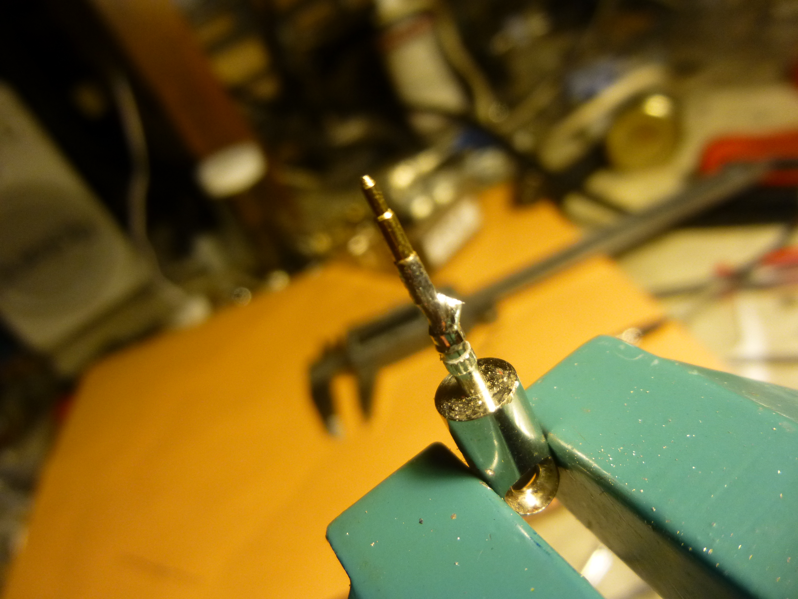
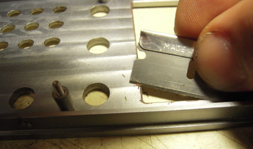
11. file or grind the excess solder around the joints. Don’t over grind, just make it level with the thickness of the spud. P1020665

P1020668

Dangerously close to drug paraphenalia and jewelry making.

12. Insert your pin assembly into the SMA base and use the Vice -Grip to push it all the way in. There should be a fair amount of resistance from the white plastic surround, which is good. As Batman said to Robin, “Push it all the way in, and don’t let it fall out.”P1020669

P1020671
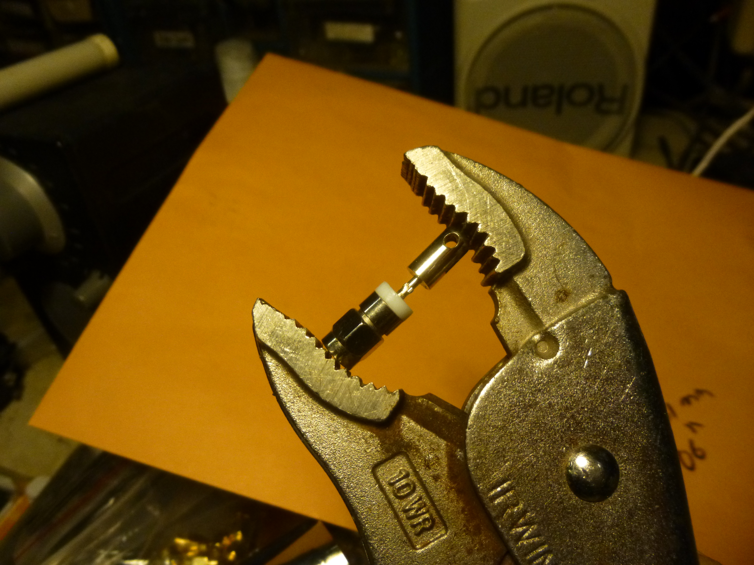
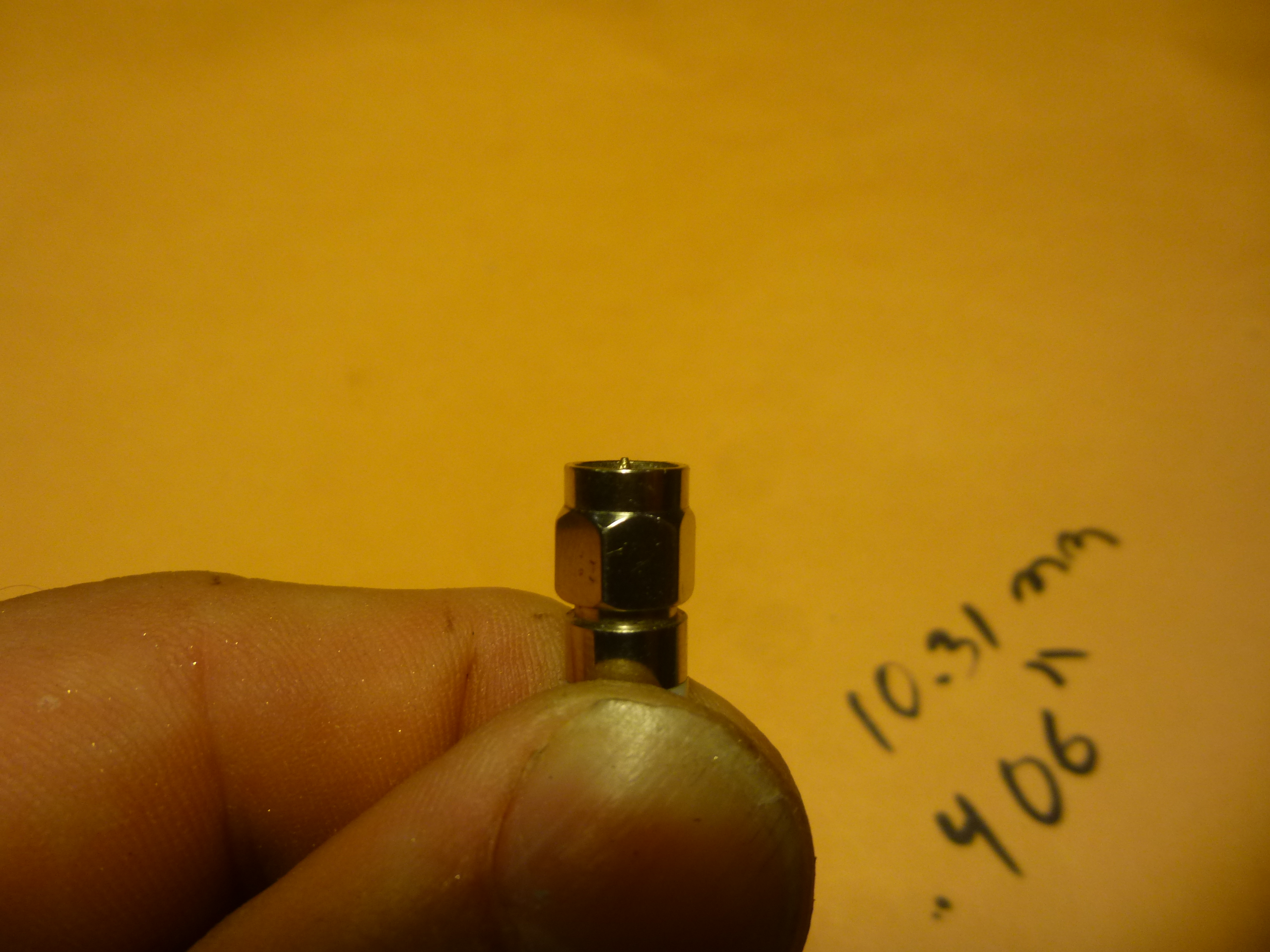
13. Make sure the new pin doesn’t protrude from the face of the SMA nut . A little is ok. If the pin protrudes too much, It will run out of receptacle on the receiver. If it came out too long anyway, you can still grind it down level with the SMA nut. If you have to grind it shorter, round it out a little, too, ok? So the pin can “find” its way into the hole. Nuff said.

14 Do a continuity test between the pin and the elbow. Should be a half-ohm or less. No continuity? You fucked up! The solder connections were bad and broke when you pushed the assembly in.

15. Take a big swig of an alcoholic beverage of your choice. (Like I am doing right now). Repeat the process on your other broken Lectrosonics SMA elbow antennas, or just buy new ones. Or ask for a trade-in at LSC, like I heard some have done. I’m not that popular. But I am tenacious.

How long will your repair job last? I don’t know.  Probably as long as the new Lectro units did, maybe longer. Ask about the warranty before you proceed. For fun, educational purposes only.

I would test periodically for continuity between the pin and the elbow.

Coming soon: how I made my own SMA whip antennas

-by Pete Verrando

Battery Technology Engineer warns against re-celling Li-ion

In my quest for some NP-1 re-celling services, My internet machine stumbled upon rathboneenergy.com. My inquiry yielded this reply:

“Hello Pete. Thank you for your email.

1st. Do NOT EVER refill, recell or rebuild ANY Lithium Ion battery. Unlike the amateurs in franchise battery companies or with fake images of their facility, I am/was a professional value added battery assembler for 23 years. Besides the extreme danger to the technician and end user in recelling Lithium Ion batteries, these idiots do not know to consider component fatigue among many other issues. With the NP1 there is also the damage to the contacts which have a tension built into them.”

Despite this company’s webpages being a confusing deluge of information, irrelevant links, politics and other ramblings, there seemed to be some evidence of engineering expertise in the field of battery technology for TV production. Rathbone’s had a booth at NAB in past years. I recall seeing his battery products on shoots over the years.

After spending 30 minutes looking for an email address on the website, I finally found one hidden in a downloadable pdf resume, after which I emailed my inquiry about re-celling NP-1 lithium-ion battery packs.

Rathbone's booth at NAB 2006

Rathbone’s booth at NAB 2006


Well… It turns out the company has gone (or been forced) out of business. The website remains as a placemarker, tribute, and resume.   But my eyes had glazed over to the point that I missed that crucial bit of information.

Nevertheless, Mr Ron Rathbone personally returned my inquiry with a 300 word broadcast battery manifesto of sorts; a tale of destruction by way of his customers,  armed robbers, politicians, and, to a lesser extent, the climate in Michigan.

Anyway, Mr. Rathbone offers the above very ominous warning, plus:

“…..in 2008, because of lithium ion, I was forced to do as the broadcast battery suppliers and go overseas to have them manufactured. To custom weld lithium ion is TOO dangerous. You must have automated assembly line to weld these cells into packs and China is the only place. So, No Matter what brand you purchase they are really manufactured in China despite what you may be told.”

from the website….Rathbone’s “no frills facility, staff at
work.”

Ritterbattery.com has been successfully re-celling our NP1 Li-ions of late. I have to wonder what Mr. Ritter thinks of Rathbone’s warning…. I’ll forward it to him and see what he says.

Screen Shot 2015-02-21 at 10.19.03 PMAre IDX batteries made in China? The batteries themselves say “Made In Japan.”  I imagine Varizoom’s batteries probably are made in China. You can pop those suckers open with a nail file. 

Screen Shot 2015-02-21 at 10.21.58 PMRathbone is a pretty deep, interesting cat, a survivor of severe hospital malpractice and 4X bypass surgery ,among other life challenges. He tells of his life-after-death experience on his blog site energyplus.com.

-Pete Verrando

It’s kinda late, but I just turned a Schoeps CMC4U preamp into a CMC5U

A CMC4U preamp from Schoeps won’t see much use these days, as “T” powering becomes less available, less popular, and technically antiquated.  What a waste!  Not wanting to destroy a perfectly functioning (and expensive) condenser mic preamplifier, this was approached with some careful deconstruction and if things went awry,  a planned exit strategy to salvage the T-power.   Planning, measuring, parts accumulation, head scratching, a couple of bad dreams and lots of solder smoke resulted in a CMC4U-turned 48 volt phantom-powered CMC5U. To our ears, it is indistinguishable from the CMC5U. This project’s been on the shelf for over 2 years, so we are happy it’s complete.interior


Now for a few shoot days to  beat it up in the field to make sure the mods hold. It takes about 9 component additions/changes, a some trace cuts, and a couple of trace bridges. Matching some component pairs, and some delicate rewiring , so you don’t melt anything or break component leads. Removal and replacement of silicon stabilizer, as some of the components are covered in it. Very good soldering and wiring skills required, and the ability not to over-work component leads or lift traces.  Anyone interested, see www.cmc4upgrade.com

by Pete Verrando

A saga of Kentli Lithium-Ion 1.5 volt AA rechargeable cells.

Many folks are very excited to see the first rechargeable Li-Ion AA battery, made by Kentli. 

KENTLI-8pcs-1-5V-2800mWh-font-b-AA-b-font-rechargeable-Li-font-b-polymer-b

Kentli AA Lithium-ion rechargeable cells and charger.


 Here’s a cut-away view of their exciting new AA cell:

so_8

The guts of a Kentli Cell.

The Kentli AA Lithium-Ion cell was perceived as an exciting development, because all Lithium Ion cells are normally 3.7 volts. So even if the cell could fit into the AA form, the voltage was too high for 1.5 volt applications.  What Kentli did was cram a 3.7 volt Lipo cell into an AA enclosure, and also stick a 3.7volt-to-1.5volt regulator inside there as well.  The charging groove (see diagram) allowed the cell to be charged directly by the charger at 3.7 volts, bypassing the “motherboard” (regulator).

Why would we want a Li-on AA cell, anyway?  The perceived advantages:

1. Ni-mH cells, the current rechargeable of choice, provide only 1.2 volts per cell.  That missing 3/10ths of a volt can really add up when using multiple cells in series (battery)! The lower voltage also increases current draw, shortening the power-up time of the cell.

2. Lithium Ion cells maintain almost their rated voltage right up till they die  Other cells, the voltage slowly drops as the cell discharges.  Many digital devices will shut-off when the supply voltage falls to a certain level, leaving much potentially live-giving energy in the cell.

3. For their weight, Lithium-Ion cells currently provide the most deliverable power than any other type of cell. They charge fast, are very reliable, and last for many charge cycles. They are also tolerant to recharging at various states of discharge.

More Advantages:

4. Rechargeable batteries create less land-fill waste.

5. Rechargeable batteries create incomeas you can bill the client for these batteries like disposables.  So, they can routinely add about $20 or more to your daily rental income, without buying disposable batteries.  Over a year, that can add up (conservatively) to about US$3000. (that’s if you work only about 14 days a month as a professional location sound mixer)

So how well do Kentli Li-ion AA cells work?

As Chinese Industry is prone to do, Kentli did some slight-of-hand marketing with these products. They listed the capacity in milli-watt-hours, so they could print that big 2800 mWh on the side of the cell.  For people who don’t pay attention, this rating gives the mistaken impression that they are more powerful than 2700 mAh (milli-amp-hour) Ni-MH rechargeables. 2700 is a common value when looking for a high quality Ni-MH rechargeable.  At 1.5 volts, 2800 mWh translates to about 1867 mAh,  so the Kentli cell technically has less power. But Kentli claims their cell lasts as long as the Ni-MH, because the regulator allows the 1.5 volts to be maintained till the cell is completely exhausted.

The street price for these Kentli AA cells is about US$11 per cell, and the charger about US$20. More expensive than Ni-MH rechargeable. They are shipped directly from China through a few distributors, including sellers on ebay.


lectrosonics smv verrando txsound

A Lectronics SMV transmitter. 1/3rd of the package is for the cell.

We bought 12 AA cells and 2 chargers to give these units a workout in our Lectrosonics SMV transmitters.  The SMV uses only one AA cell.  A disposable Energizer Lithium AA will power it for 5 hours (the longest). The best NiMH rechargeable will power it for about 3.5 hours.

And the result? A fresh Kentli AA, right out of the box ,will power the SMV for 3.5 hours. Same as a high quality, 2700 mAh Ni-MH rechargeable.

But here’s the rub, in a few easy steps.

1. In my application, Kentli AA’s take their internal cell from a full charge to near-exhaustion in every cycle. Over the long term, I think Li-Po rechargeables prefer a lighter charge-discharge cycle. so with this workout, these Kentli cells won’t last for very many cycles. A Lectro SMQV would treat the cells more gently, distributing the current draw between two cells, and possibly resulting in better performance.

2. Kentli AA’s use a 3.7v Li-Po cell and convert it to 1.5 volts. There is inherent inefficiency in this conversion process.  The Lectro SMV then takes the 1.5 volts and inverts it up to 5 volts, and 3.3 volts, to serve the various internal functions. Every time you convert a voltage, you lose some efficiency and power, in the form of heat.  The Kentli is already stretching the capacity to the max of its tiny 3.7 volt, 760 mAh cell, every time it is charged and used. With the SMV, there are multiple conversions, and those power losses add up.

3. These days,  the “power down” mode of many devices is not a true power-down. Even after its turned-off, the SMV draws a tiny “quiescent current.” This is simply power to enable the SMV to power back up with a momentary button-push. The Kentli sees this quiescent current, and therefore keeps its motherboard alive, affecting a continuous drain on its cell. So leave a freshly charged Kentli in the SMV overnight, and it will be dead in the morning.

4. Maintaining AA rechargeables for location sound use is a pain in the ass. They get lost easily. I lost one in the snow on the very first shoot! They are difficult to keep separate between used and unused. They require chargers to be travelled and plugged-in. They require extra time to sort and charge and check at call and wrap.  They create a level of uncertainty in the production process. Will this be the shot when the battery dies for good?

5. And obviously, in the SMV, a rechargeable will run for only 3 hours, and a AA li-ion disposable will burn for 5 hours.  In most cases, 5 hours is enough time to get us to lunch, when the battery can be replaced.  The SMV is designed to accept a cell that swings from 1.9 volts to .9 volts, and before it dies, will suck every last ounce of power from the cell!

6. Don’t talk to me about the Lectro SMQV, the double AA version. I know they will run twice as long. I don’t care. I like the smally-small SMV for so many reasons. I use it as a drop-weight when running the lav cable down shirts and blouses and pant-legs. The SMQV is almost as large as a UM400A, Lectros classic 9-volt transmitter, of which I already have a shit-ton.  The SMV is great for use on children, with their tiny pockets and elastic waistbands. It also has the lowest profile in a pocket or bra-strap.

Oh, and the Kentli Chargers tend to die. 

kentli charger txsound

The Kentli Charger with its ring-groove contacts. They contact directly with the Li-Po battery and charge at 4.2 volts.

kentli, location sound mixer, txsound.com

The innards of the Kentli AA charger

P1010256

A 5 volt phone charger inserted into the 5 volt rails of the Kentli charger. Fixed!

Of the two Kentli chargers I originally ordered, one died a couple of months in. The dealer asked for photographic proof that the charger was dead. They sent a replacement from China, which never arrived, and then sent me another.  Eventually I received both chargers, so now I had four. Then the other 2 chargers immediately died.  Taking this opportunity to either throw away the dead chargers, or take them apart, what do you think I did? The charger consists of a very flimsy switching power supply converting your AC house current to 5 volts DC. The voltage is then applied to a smart charging circuit for the AA cells. The flimsy switch-mode supply was the obvious culprit, so it was replaced with an outboard 5 volt phone charger, of much more robust design. So now we have 4 chargers.


Then, the Kentli AA’s start to show signs of age.

This is about the time that the Kentli AA cells stopped delivering 3 hours of power to the SMV’s.  This is not the cell you want in a transmitter that goes out on a competition shoot, where you don’t have access to the talent once the action begins. I would guess I got about 100 charges on my Kentli’s before they began to show signs of expiration. The chargers show a full charge even on the cells that have stopped performing. In a less-demanding environment, (like an LED flashlight or an ipod dock) they may give better service.

And Alas! one Kentli drops to the floor and pops open like a Zippo Lighter! (Also the shrink wrap on the cell will begin to tear and peel with daily use. )

kentli AA txsound.com

Pops open like a Chap-Stick!

kentli txsound sound mixer verrando

The Kentli regulator board.

UPDATE : Curious about the quiescent current draw of the Kentli Cell, on its own, we hooked up a micro-amp meter between the regulator board and the Li-Po cell. The result:

kentli AA self discharge txsound

Kentli AA cells discharge on thier own, with a constant current draw of 29 microamps from the internal “motherboard.”

You guessed it. The Kentli motherboard is drawing 29 microamps from the cell at all times.  By comparison, Lectro transmitters, when powered down, draw about 5 microamps from the cell.  This is in conflict with the advertising claim made on the Kentli promotional material:

discharge claim kentli txsound.com

Advertising claim from Kentli’s promotional materials

 P1010251And whats this? A 3.7 volt, 2.66 wH li-po cell! That’s 2660mWh, or 718 mAh! Not 760 mAh, as the label claims!

So there’s no doubt the Kentli folks are really pushing the envelope with this initial attempt at a 1.5V Lithium-Ion rechargeable. A little more conservative design paramaters are required for location sound use. But for flashlights and home use, I’m sure theres no telling! And no telling of what’s to become of my little AA canisters for a location sound mixer on the road!

First Adopter, Last Responder

The Zaxcom Nomad one of the latest devices offered for production sound mixers. It offers multi track recording and mixing, in about the same footprint as a traditional 4 or 5 channel mixer. It is not a collection of afterthoughts, like the Sound Devices 788T/CL8. Nevertheless, it is new, and does not have many hours racked up in the field. Its also a complex device, and new-gear bugaboos are inevitable. 

The Zaxcom Nomad

Following a popular sound mixer discussion group, a few reactions become evident.
1. Many newer sound guys who’ve had a mixer-only package are upgrading to this device.
2. There’s still a few tweaks and quirks in the device that are being discovered while on the job.
3. Those who have problems quickly detail their production horror story on the discussion group.
4. The good or uneventful experiences go un-documented.  

I’ve never been a “first adopter.” Why would anyone bring a 1st-generation device, right out of the box, to a paying client’s job? The producer is not paying me to experiment with new gear. My gigs are not beta-test sites for new equipment.   Granted, equipment issues happen on the job, even with time-proven gear. That’s why its important to have an intimate knowlege of how your gear works, and even some ability to fix it. Which I do. Also back-up gear is important to bring along if ever things get really nasty.

Back when DAT became the standard recording device, many mixers continued to roll their analog Nagras as a backup. Two recorders on the cart. It was cumbersome, but the peace of mind of having a backup was sublime. Those DAT machines were quirky animals, so much as an errant speck of dust could shut them down. When they were finally obsolete, we sound mixers built a huge bonfire and threw all our DAT machines on it. Not really. But I still have my DAT machine, so if you ever want to have a bonfire, I will be the first to throw mine on. 

There will never be a Nagra bonfire, because they are just too beautiful a machine to trash.  As a hobby,  I restore and sell Nagras to audiophiles.  Nagras are the ultimate refinement of the analog recording medium. 

So, if your soundman comes to the job boasting of a new piece of gear, raise an eyebrow. Make sure your production won’t be featured as the next dirty-laundry story on a popular sound mixer discussion group.

Please visit my website www.txsound.com

IDX NP-7LS Battery- Back From the Dead

It’s a shame when a high quality Lithium-ion rechargeable dies. Throw one away, and there’s a lot of sophisticated charging technology you’re throwing away with it.
NP-1’s are popular rechargeable batteries for location sound applications. They were originally created for powering professional cameras and VTR’s.
Today, a Lithium-ion NP-1’s costs about  US$ 180 to $225, depending on brand.  In the Li-Ion category, chargers and batteries are typically not compatible across brands.
New cells for the NP-1’s can be purchased individually for about eight dollars each. But creating a reliably-soldered series-parallel pack for an NP-1 is probably more trouble than its worth.
I picked up a couple of VariZoom brand NP-1’s before realizing they are not compatible with my IDX chargers. The IDX will charge them partially before exhibiting a fault condition. So the VariZooms collected dust on my shelf.
Then I was given some IDX NP-7LS NP-1’s that had been purchased but never used. About 8 years old, they would not accept a charge. So off to the shelf they go.
What follows is a happy marriage between the two brands, and a couple of like-new IDX NP-1’s for me.

Time lapse Deva Fusion Multitrack breakdown, repair assemble

After a recent rainy shoot, fader #3 started behaving erratically. The fading action would jump around, regardless of the fader’s position. I ordered a new pot and replaced the fader, but this did not cure the problem. Going back in, I re-soldered the new pot and also re-soldered a past repair on fader #3, which was probably the issue,a Surface mount resistor. I don’t have a proper SM soldering iron, so I had to wing it with a pinpoint soldering tip. Normal soldering tips can obliterate an SM component and the surrounding traces.
by Pete Verrando

Fusion teardown to remove faceplate dirt

Poor R3. Explanation below.

The Zaxcom Fusion series of touch-screen multitrack recorders are designed for field use, but after a few months, dirt accumulation around the touch-screen can impede functionality. I’ve torn-down my Fusion to clean the dirt accumulation, and took some photos to document the process. This is more of a documentation, and less of a how-to. I disavow any responsibility to those who attempt to use this as a guide.

There’s also some rules broken here that I normally don’t break.  I should have had an nice ice-tray to keep all the nuts and bolts organized. I should have also cleaned up my bench before starting ! Also, one should be very careful around Surface-Mount circuit boards as the miniscule components can break off with an errant bump of a screwdriver, and you’ll never be the wiser, until you’ve re-assembled the machine and something doesn’t work.

After the main cover is removed, the Fusion presents thusly:

All the knobs get removed as well. Then there’s the business of removing the faceplate from the body, attached with side screws. The multi-pin connectors on the back of the faceplate need to be carefully loosened and disconnected.

There’s also a pair of wires that must be disconnected from the mic-input board- these are for the slate mic. The connector can be carefully loosened off the input board with a small screwdriver.

The slate mic connector is the small white one right under the 25pin d-sub.

The red-black wires at the bottom are the slate mic wires. The connector is right above the headphone jack.

The front panel, still hanging on by the slate mic wires.
Once the frontplate is disconnected from the box, the gentle operation of removing the nuts surrounding the circuit board can proceed. A nut driver is preferred. If you use a pair of needle-nose pliers, you risk slipping off the nuts, and crashing into one of the surface-mount components, breaking it. Like I did.
Lucky I know how to solder surface-mount components. I wacked into R3, very close to a nut.
For God’s sake, use a nut-driver, not a pair of needle-nose, like I did.

Once all the nuts are removed, hold the assembly faceplate-up  for separating the circuit board from the aluminum front plate. If you have it circuit-board up, the LCD screen will fall out of its holder, and hang by its ribbon cable, which is unsettling. So hold it faceplate up and separate the pieces carefully:

Here is the circuit board with the faceplate off. Be very careful, the surface-mount components on the underside are fragile!
The LCD screen will fall right out of its holder, so handle it carefully. At this point I removed all the dirt that accumulated on the screen edges, between the buttons, and around the potentiometers.
Dirt accumulates/sticks to the edges of the screen.
Dirt surrounding the pot shafts
Dirt around the edges/at bottom of button assembly
And most importantly, I scraped off the sludge that adheres to the underside of the faceplate:
yucky
After cleaning, re-assembly is easiest by holding the parts vertically, so the LCD screen doesn’t fall out of its holder, and the screws can be lined up through the holes of the circuit board. Then, flipping it over like a sandwich,  All the nuts can then be carefully tightened on the component size of the circuit board.  Careful around those SMT components!!!
Re-assembly is the reverse of disassembly, but it is difficult to get the slate mic connector back on its pins. The easiest way to do this is by loosening the DB25 d-sub output connector, and pushing it in the box. This creates an access hole to push on the slate mic connector. You can also see me adjusting the potentiometer for the audio level of the slate mic. My level arrived from the factory very hot.
I fully test the machine before final re-assembly, I want no surprises on the job. Remember- in my first attempt, I bumped a pair of pliers into R3, a tiny surface-mount resistor. I didn’t realize my error until testing, when fader #3 refused to post fade.  Magnifiers and a steady solder-hand were required to find this problem and repair it.  If I had used the right tools, I’d have saved a bunch of time.
Maybe I should build a one-room apartment in there…
Even after cleaning up the dirt accumulation under the faceplate, a single dusty/dirty shoot can restart the ingress of dirt inside the recorder. Using fingers, a firm and gentle pushing down of the LCD from all four corners will often free the debris. I believe Zaxcom has recently added a machining process to the aluminum surrounding the LCD to minimize this problem. Of course, if your machine lives on a cart, dirt accumulation is less of a problem. However I just finished a bag job, hog hunting in the Rio Grande. I’m sure I’ve brought home some of that good red clay inside my Fusion!
-by Pete Verrando